
The Idle Hunt: Diagnosing an Intermittent Near-Stall With Nothing But OBD-II Logs
For about three weeks, my 2010 Ford Fusion (2.5L Duratec I4) would occasionally hunt at idle and dip close enough to stalling that it got my attention every time. No check engine light. No stored codes, ever. Just a car that would sit at a stoplight, RPM wandering, and every so often drop hard enough that I'd instinctively cover the brake.
That combination - a real, repeatable-feeling symptom with zero diagnostic trouble codes - is the annoying case. A DTC gives you a starting point: a pinpoint test, a wiring diagram, a "check this sensor first." With nothing stored, the only signal available was whatever I could log myself. So that's what this became: not a wrench problem first, but a data problem, and only a wrench problem once the data pointed somewhere specific.
This is the writeup of how that went, including the two dead ends that ate the most time, the methodology that eventually cracked it, and the OEM documentation that independently confirms it - worth knowing about if you're chasing anything throttle-body-shaped on a 2009-2013 Ford Escape, Fusion, Mercury Mariner, or Milan.
Setting up the only instrument I had
With no scan-tool code to chase, the plan was to log every idle/drive session with a phone-based OBD-II logger (Torque-style trackLog CSVs) and go looking for whatever sensor misbehaved around the hunts. Over about a month that turned into 30 separate log files. A few things about that data turned out to matter more than the actual sensor readings:
The PID set isn't stable across sessions - because the approach was to cast a wide net first and narrow deliberately. The first logs carried as broad a channel list as the phone logger would allow (fuel trims both banks, wideband O2, catalyst temps, GPS accelerometer), on the theory that any of them might turn out to matter. Once a run of anomalous datapoints started showing up - cross-checked against handwritten wall-clock notes of exactly when a hunt or near-stall happened - the active PID list got narrowed on purpose for later sessions: Long Term Fuel Trim dropped out, Engine Coolant Temperature and EGR Commanded/Error got added in, favoring the channels that were actually earning their keep. Any cross-session comparison has to check each file's own header before assuming a channel is even present - assuming otherwise silently drops rows or, worse, silently substitutes a different column.
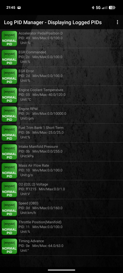
A "10Hz" logger is not sampling every channel at 10Hz. This is the single most important thing I learned about generic OBD-II logging, and it will bite anyone doing this kind of analysis. The logger writes roughly 10 rows a second, but it's polling the OBD bus round-robin - each individual PID only actually refreshes every ~1.0-1.4 seconds (coolant temp: about every 10 seconds), and the poll order is fixed. That means the ~10 rows/second you see in the CSV are mostly repeated values from the last poll of each channel, not ten independent readings. Two direct consequences: you cannot make any claim about which of two channels "moved first" at sub-second resolution (the poll order alone can manufacture a false ordering), and a fault that opens and closes in under a second can fall entirely between polls and simply never appear in the log.
Long stretches can be silently frozen. A dropped Bluetooth connection makes some loggers keep writing the last-known values while the timestamp keeps advancing - bit-identical consecutive rows for minutes at a time. Any idle-stability statistic computed over those rows is measuring nothing. Filter them out before you trust a "clean idle" number.
GPS speed lies at rest. Reading exactly 0.0 with no real fix (parked in a garage, weak signal) looks identical to a real stop. Where available, OBD vehicle speed is the more trustworthy "is the car actually stopped" signal.
None of this is throttle-body-specific - it's just what's true of consumer OBD-II logging in general, and it shapes every conclusion below.
Dead end #1: the vacuum leak that wasn't
A rolling idle hunt is the textbook symptom of a vacuum leak, so that was the first hypothesis, with the brake booster diaphragm as the leading suspect. Two lines of evidence killed it:
- Fuel trim. A leak big enough to visibly hunt a 2.5L idle typically drives idle Long Term Fuel Trim to roughly +10% to +25%; even a small, benign leak tends to sit around +5% to +8%. The logged value was -1.10% mean, maximum exactly 0.00% - a well-metered engine, not a leaky one.
- Directly measured vacuum. Manifold absolute pressure is trivially convertible to vacuum once you know local barometric pressure - and barometric pressure is recoverable from the very same log, for free: read MAP with the engine off and settled, and it equals ambient. On a clean, parked, foot-off idle window, that worked out to 19.5 in-Hg of manifold vacuum - solidly mid-spec for this engine, not the low, borderline reading a real leak would produce.
The one thing neither of those closes is a leak that opens and closes in under a second - Long Term Fuel Trim (LTFT) is a slow-moving average and would never register it, and per the poll-rate limitation above, a sub-second event can vanish between samples entirely. A smoke test stayed on the list as a cheap parallel check for exactly that reason, even after the leak theory got demoted from "leading" to "unlikely."
Dead end #2: replacing the MAF sensor
Repeated "airflow drops, throttle barely moves" signatures around several early dips pointed at the mass air flow sensor, which got replaced. Idle got measurably less stable afterward, which read at the time like the wrong part had been touched.
It wasn't the MAF's fault, and figuring out why took two separate corrections:
The "MAF spike" signature was a logging artifact, not a sensor fault. Once the fixed poll-order behavior above was understood, the specific "airflow blips while throttle looks flat" pattern that had been read as spurious MAF spikes turned out to be the normal, expected shape of an ordinary pedal release or engine shutdown, sampled through a MAF channel that updates exactly 0.5 seconds before throttle position on every poll cycle. Eleven "spike events" evaporated under that correction.
The apparent post-replacement worsening was an unlogged confound, not the new part. Comparing idle airflow at matched RPM across sessions showed swings of 50-70% that had nothing to do with the sensor: accessory load (A/C compressor) and gear state (Park vs. Drive) move idle airflow that much on their own, and neither was ever recorded in the log. Two sessions logged five days apart, one parked at night and one idling in traffic during the day, showed exactly the airflow difference you'd expect from that difference in load - not from a miscalibrated replacement part. This turned out to be the single largest uncontrolled variable in the whole dataset. If you're doing this kind of before/after comparison on your own vehicle, write down accessory and gear state by hand every time you log - it's the one thing a generic OBD-II PID list won't give you, and it's large enough to make a clean sensor swap look like a regression.
Neither of those corrections would have been possible from statistics alone; they came from going back to the raw per-row data and reading the actual timestamps and values around the disputed events, not trusting the summary numbers.
The discriminator that actually worked: which way manifold pressure moves
The physically clean test for "what caused this specific RPM collapse" turns out to be the direction manifold pressure moves, not airflow:
| Cause | MAF | Absolute MAP | Why |
|---|---|---|---|
| Throttle flow area reduced (plate closing, binding, restriction) | falls | falls (vacuum rises) | Engine still pumping near idle speed, less air admitted |
| Misfire / ignition dropout / crank sensor signal loss | falls | rises | Engine decelerates, pumps less, manifold refills toward atmospheric |
| Fuel delivery dropout | falls | rises | Same mechanism |
| EGR valve leaking/stuck open | falls | rises | Inert exhaust mass added to the manifold |
| Sudden accessory load step | rises then falls | rises | PCM opens throttle to compensate, load droops RPM anyway |
MAF falls in every one of those rows - it doesn't discriminate anything. MAP direction does, and cleanly: a misfire, a crank-sensor dropout, a fuel-pressure loss, and an EGR leak all raise absolute manifold pressure, while an airflow restriction is the only one that lowers it. Every recorded RPM collapse with manifold pressure logged showed pressure falling - meaning air being restricted, not combustion being lost. That single fact ruled out the misfire/crank-sensor theory the symptom would otherwise suggest (there was never a misfire code either), and pointed everything downstream at something that reduces throttle flow area: the plate itself, or what drives it.
The event that made the case: a 90-second near-stall
The clearest single piece of data was a ~90-second disturbance, RPM hunting between roughly 520 and 1,205, that a full-dataset sweep found extracted from one recording. Pulling the raw trace for that window and plotting RPM, manifold vacuum, and spark timing advance together shows the shape of what the idle controller was doing the whole time it was fighting to keep the engine alive:
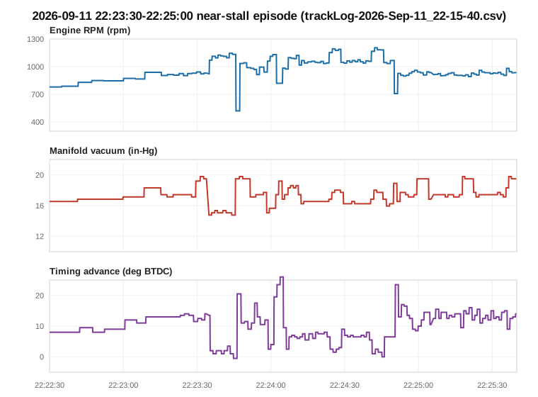
RPM (top), manifold vacuum (middle), and spark timing advance (bottom) through the same ~90 seconds, read directly from the raw trackLog. Timing pinned near zero or negative while RPM sits high, then slammed to +20-26 degrees as RPM collapses - the PCM burning nearly its entire idle-timing authority in both directions.
Two things about this shape, beyond the single-episode caveat that any n=1 event deserves:
- The baseline itself was wrong before anything visibly "dipped." RPM climbed roughly 150-275 rpm above what the engine's own warm-up curve says it should have been running at that coolant temperature, and held there for the better part of a minute before the first trough. That's not warm-up drift; the idle controller was already fighting something before the first obvious event.
- The PCM's response is the tell, not just the RPM number. Retarding spark at idle is a normal, routine way to trim torque down quickly - but retarding it down to -0.5° while simultaneously seeing airflow nearly double is the PCM fighting air it didn't ask for, not commanding a deliberate high idle. Ten seconds later the same loop reversed: airflow dropped 66%, RPM fell from 1,132 to 520, and timing swung to +26° trying to save it. That's the signature of a control loop whose actuator has hysteresis or stiction - it doesn't track small commands smoothly, it sticks and then jumps, and every correction overshoots.
A separate, unrelated event a day earlier added a second, independent line of evidence: the throttle position PID pinned at 18.4% - exactly the plate's spring-default resting position - while the accelerator pedal was at 87%. That's the actuator motor de-energized and the return spring taking over: the throttle module's own failsafe kicking in, caught mid-fault.
The test that a phone logger can't do
Everything above narrows the suspect list to "the throttle body assembly," but it can't distinguish why the plate moved: did the PCM ask for a smaller opening and the plate over-delivered, or did the plate move on its own? Answering that means comparing commanded throttle angle against actual throttle position, logged through a real event - and that's where a generic Bluetooth OBD-II adapter runs out of road.
Commanded throttle angle on this platform is Ford's proprietary TAC_PCT PID, which lives on the
vehicle's MS-CAN bus - a separate physical bus from the standard OBD-II broadcast (HS-CAN) that
every consumer logger uses. A plain ELM327-style adapter cannot see MS-CAN traffic at all,
regardless of which app or custom PID definition you throw at it; it's a hardware limitation, not
a missing PID. Getting at it requires FORScan on Windows with an MS-CAN-capable adapter
(an STN1170-based unit; OBDLink EX/MX+ and similar are commonly cited as working).
Four independent FORScan captures, logged continuously through real hunts rather than spot-checked at a quiet idle, all showed the same thing: actual throttle position collapsing (roughly 4.5° down to 0.2-1.3°) while commanded angle stayed flat or, in one capture, moved the opposite direction. The plate was not doing what the PCM asked it to do. That result also directly excludes a vacuum leak (a leak has no physical path to move a position sensor), the PCM itself (it never asked for the closure), and a TPS wiring fault (both redundant position sensor signals tracked the plate's actual movement in full agreement, they just agreed on the wrong position) - leaving the throttle body's own actuator motor or plate as the only thing consistent with every observation.
Independent confirmation: Ford's own bulletin and NHTSA's investigation
Independent confirmation that this is a known failure pattern for this platform comes from Ford Customer Satisfaction Program 13N03, "Certain 2009 Through 2013 Model Year Fusion, Milan, Escape and Mariner Vehicles - Throttle Body Extended Coverage," backed by NHTSA's closing resume for Preliminary Evaluation PE13-003 (both linked in References below). Ford's own bulletin language, quoted directly:
"Affected vehicles may develop contamination on the internal motor contacts of the Throttle Body, resulting in intermittent electrical connectivity. If this condition is present, the Malfunction Indicator Lamp (MIL) or Wrench light will illuminate and the vehicle may enter a Failure Mode Effects Management (FMEM) of default throttle position with fixed RPM."
And NHTSA's own summary of the underlying mechanism, from the PE13-003 closing resume:
"The ETB internal motor contacts may develop a high resistance material buildup condition on the commutator, resulting in intermittent electrical connectivity and reduced engine power."
Worth being precise about what Ford's actual engineering fix was, since it's easy to assume the contact-wear mechanism itself got redesigned away. It didn't. Per the same NHTSA resume, Ford and its suppliers (Delphi and Igarashi) shipped two changes: a PCM software update adding a throttle-body motor cleaning cycle at key-on, and a hardware revision to the actuator motor's internal components - design, surface finish, and material composition (including a new brush material) - to improve durability. That's a better brush and a periodic self-cleaning routine on an otherwise still-brushed DC motor, not a switch to a contactless (Hall-effect) actuator that would eliminate the wearable contact entirely. The TPS side of this assembly, separately, had used a Hall-effect sensor ASIC since the earliest documented part revision on this platform - so the contact wear in this failure was never in the position sensor to begin with, only in the motor's own commutator.
The program extends throttle body warranty coverage to 10 years or 150,000 miles from the
vehicle's warranty start date, covers exactly this vehicle line and engine (Fusion 2.5L DOHC is
labor code 13N03F), and names the same replacement part (DS7Z-9E926-D) that independent parts
research had already identified from the physical assembly. NHTSA's investigation logged
essentially the fault signature described above - reduced power at idle, MIL/wrench light,
Failure Mode Effects Management defaulting the plate to a fixed low-RPM position - across nearly
12,000 complaints on close to 1.6 million affected vehicles before Ford issued the program in early
2014.
The fix
Motor-only replacement got a real look before the assembly did, not an afterthought: the actuator
motor's own stamped number (28110350, visible in the teardown photos below) was checked against
parts catalogs and motor supplier listings and didn't resolve to anything purchasable - it reads
like an internal manufacturer lot/date stamp, not a SKU. Every OEM and aftermarket source for this
platform sells the throttle body as one sealed assembly (motor, gear train, and integrated TPS
together), with no separately serviceable motor. That ruled the option out on its own, without
needing to weigh cost or labor against it.
- Part: an aftermarket electronic throttle body assembly, 6-terminal, integrated TPS, new (not
remanufactured), cross-referenced to OEM part numbers
9L8Z-9E926-A,DS7Z-9E926-A, andDS7Z-9E926-D- the last of those the same number named in Ford's extended-coverage program above. - Install: 4 bolts, 10 Nm / 89 lb-in, new gasket.
- Relearn: FORScan PCM service functions - Reset All Adaptations, then a full module reboot (this PCM has no separately named throttle-relearn function; this combination is the equivalent). Followed by a key-on/engine-off wait for the automatic throttle sweep, a full warm idle, and a short mixed drive to relearn transmission shift points.
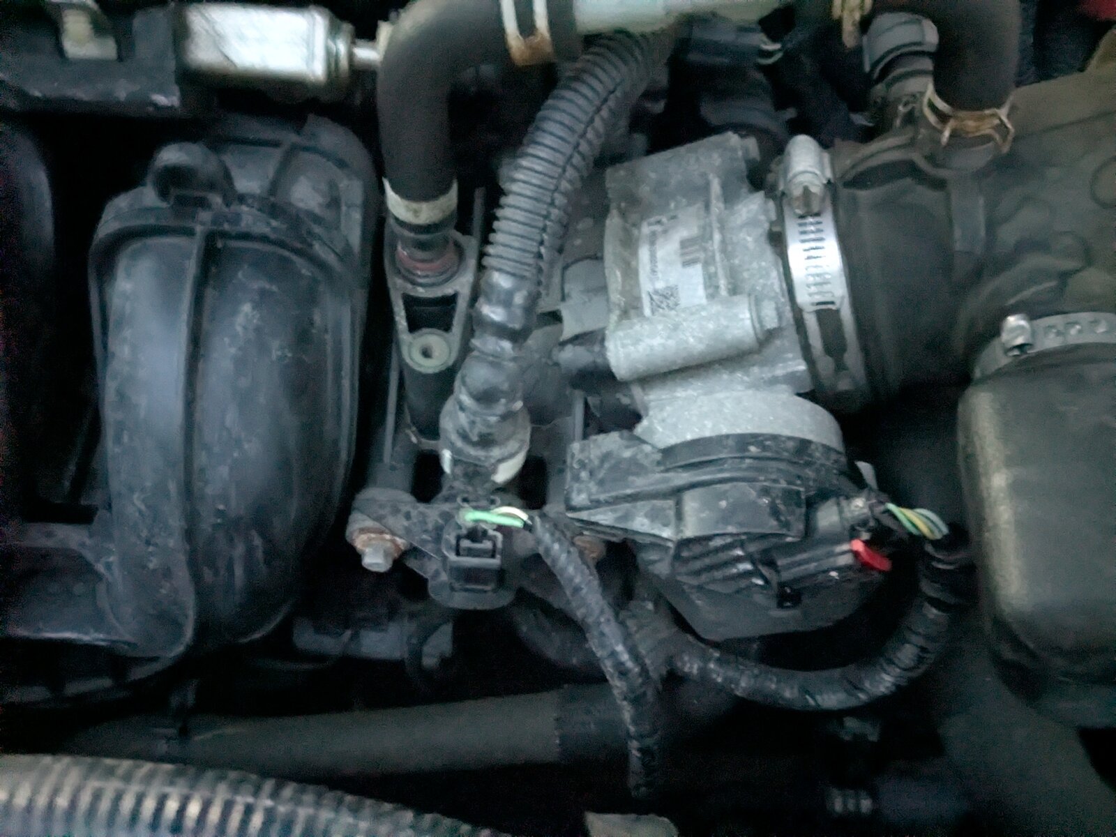
Post-mortem: what was actually inside the failed throttle body
Before the old assembly went in the trash, it was worth opening up - partly curiosity, partly to see whether the physical evidence matched the "high-resistance contact buildup on the commutator" language from Ford's Customer Satisfaction Program 13N03 quoted above, rather than just taking the bulletin's word for it.
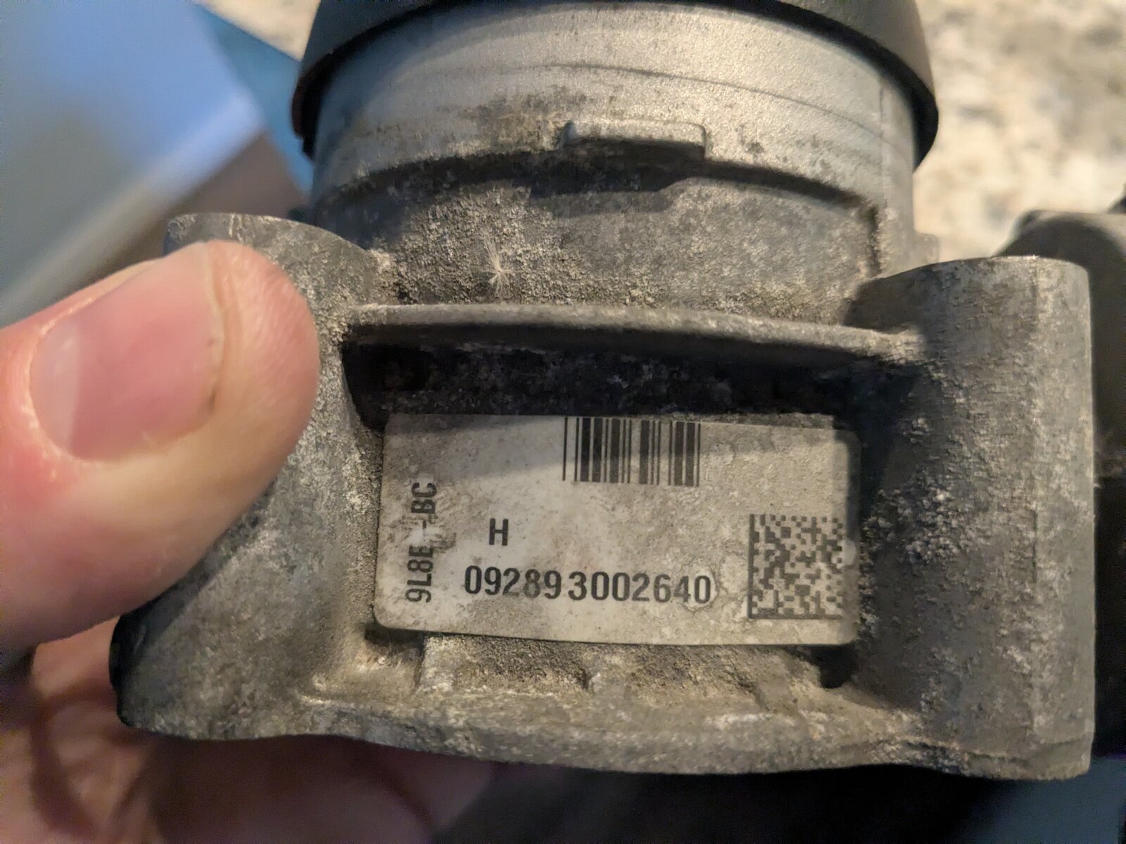
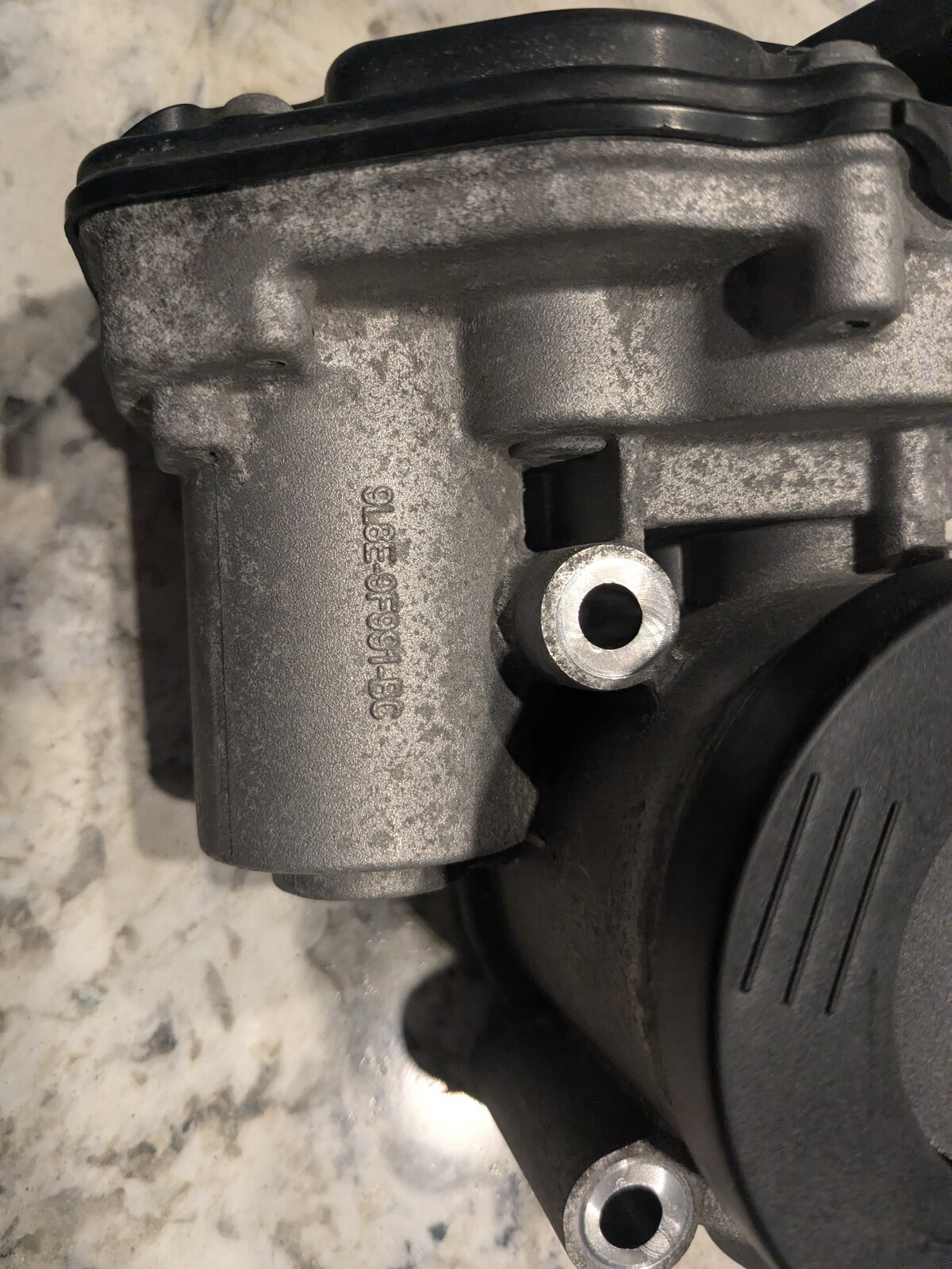
The label under the connector tab reads part number 9L8E-9F991-BC - a casting/assembly number for
the motor housing, distinct from the DS7Z-9E926-D full-assembly number cited in the extended
warranty program (which covers the complete throttle body including the intake flange and TPS, not
just this sub-housing).
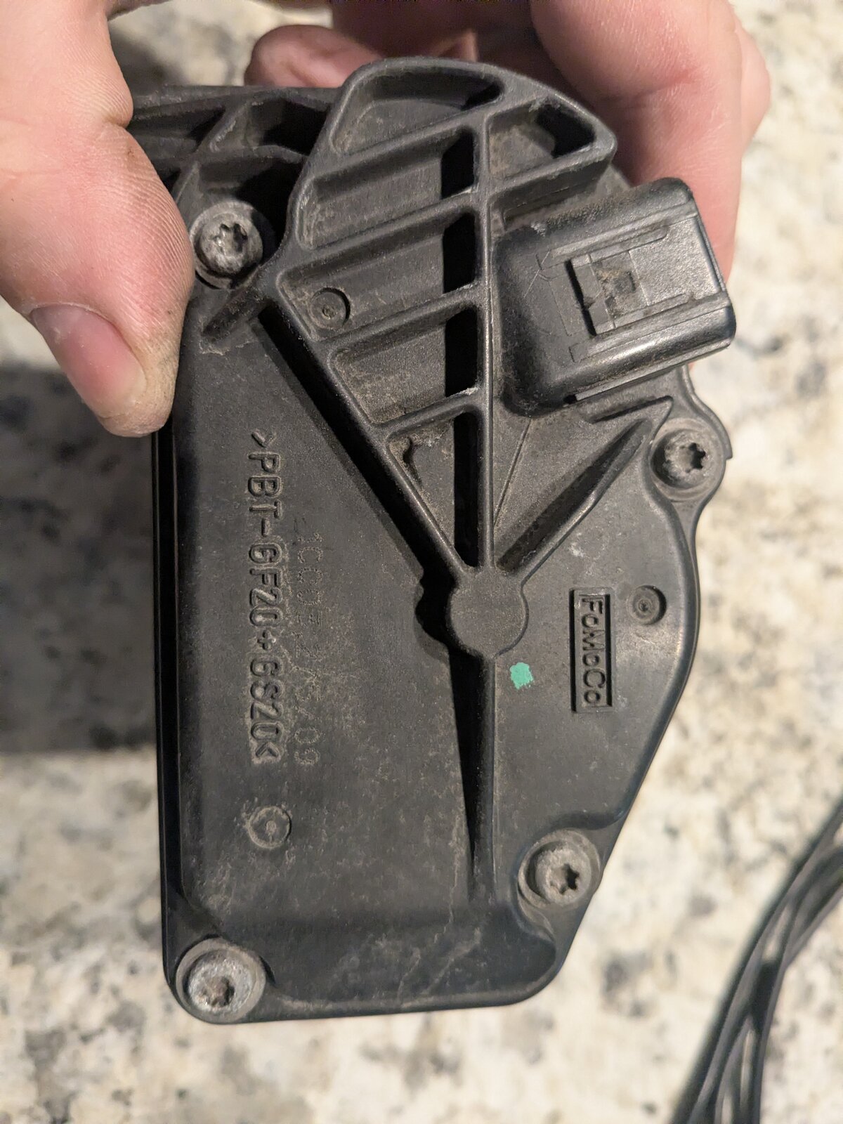
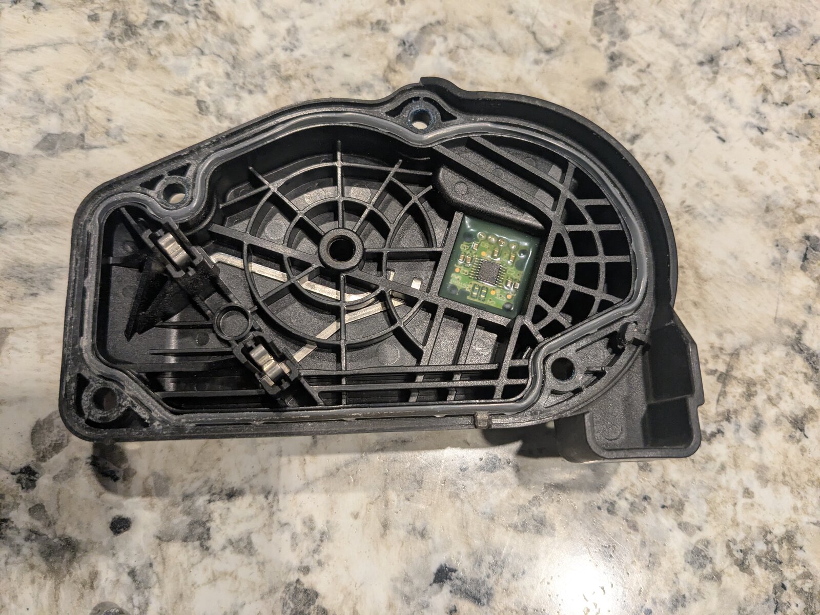
Four screws hold the cover over the gear train. Inside it, opposite the gears, sits the throttle position sensor board - a small PCB with a Hall-effect ASIC, matching what the mechanic-findings doc had already concluded from the FSM: the TPS side of this assembly is contactless and was never the wearing part.
Behind the cover is a two-stage reduction gear train: the motor's small pinion drives a large brass sector gear, which in turn drives the final output gear carrying the position-sensing magnet and the throttle shaft itself.
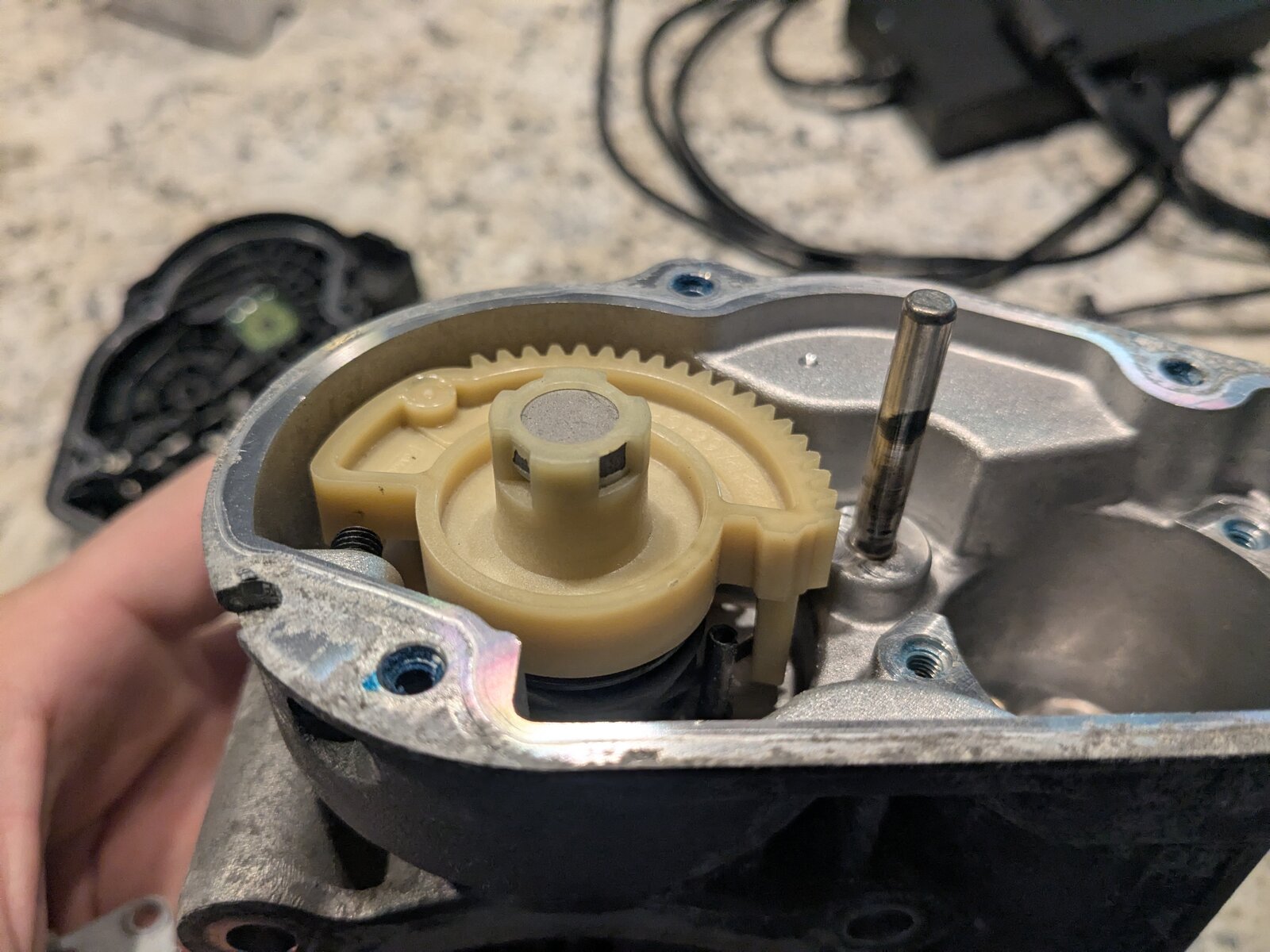
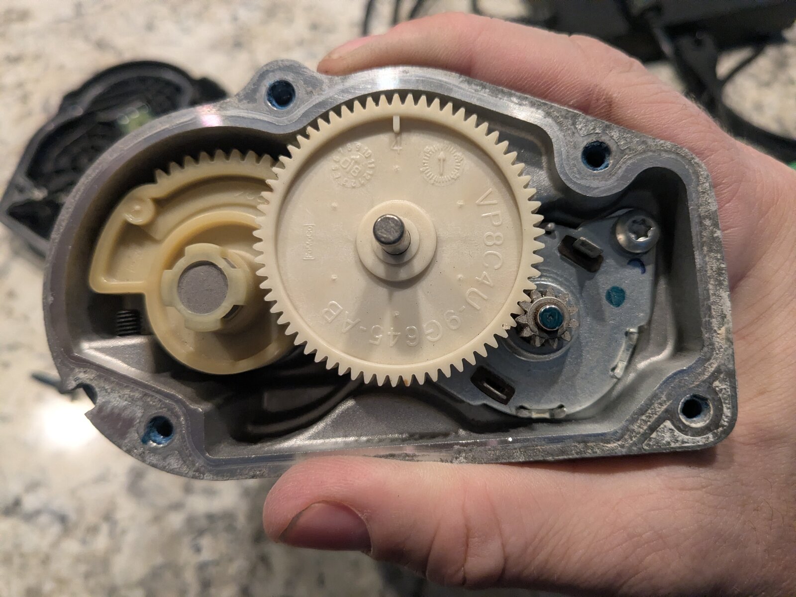
The final output gear - the one carrying the throttle shaft and the position-sensing magnet - is
itself stamped with a supplier part number, VP8C4U-9GG45-XB, separate from the 9L8E-9F991-BC
housing casting number above. Two different numbers on two different sub-components of the same
assembly, which is normal for a part built up from several suppliers' pieces rather than a single
casting.
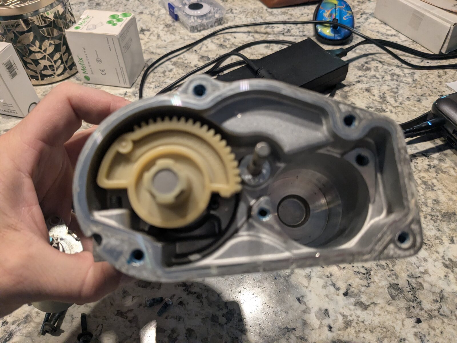
Pulling the motor out of its bore was the point of the whole teardown: the actuator motor is the part Ford's bulletin specifically calls out, and the part the FORScan commanded-vs-actual capture had already pointed to as the fault.
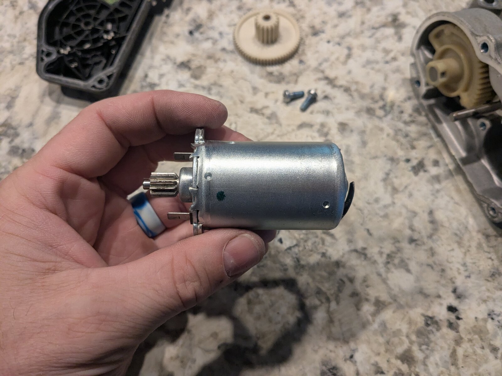
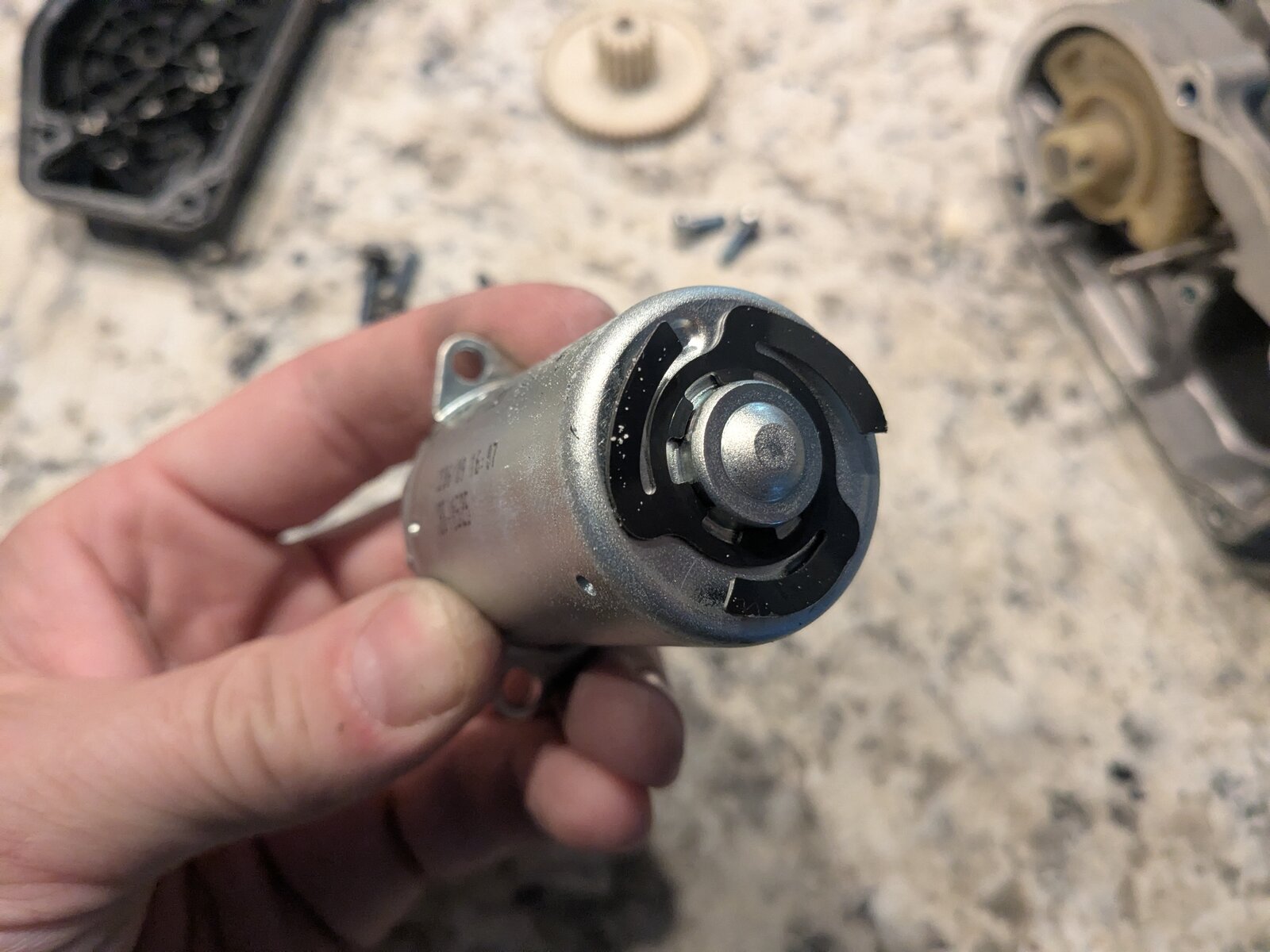
Flipping it around to the commutator end is where the bulletin's language stopped being abstract:
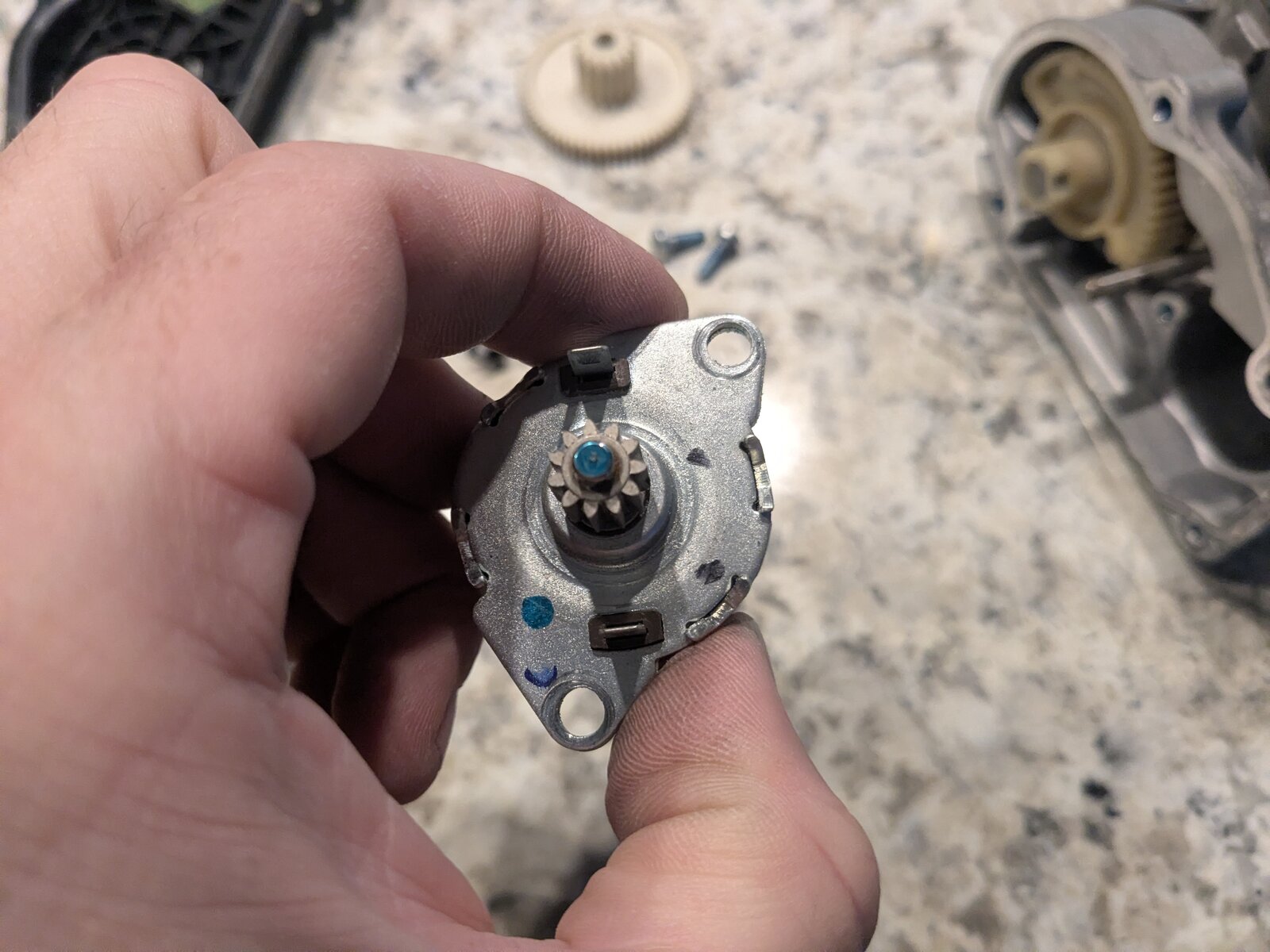
That's the "internal motor contacts" and "commutator" Ford's Customer Satisfaction Program 13N03 and NHTSA's PE13-003 closing resume both describe - visibly discolored where the brushes ride, which is the physical signature of the high-resistance buildup those documents describe causing intermittent connectivity. It's not a smoking gun in the sense of a lab analysis, but it's consistent with every piece of downstream evidence already gathered: a plate that stuck and jumped instead of tracking smoothly, and a fault that came and went with no consistent trigger.
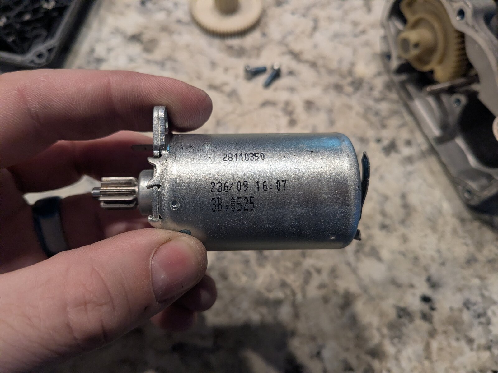
The motor's own label carries its own part number, 28110350, plus a manufacturer date code -
236/09, read as day 236 of a production year ending in 9 - which, if that's 2009, puts this
motor's manufacture right at the front edge of the 2009-2013 model range the extended coverage
program targets. Consistent with an original-equipment part that was never replaced before this
failure, not a prior warranty repair.
Verification, and why one clean drive doesn't count
Three post-repair sessions, roughly 48 minutes combined, came back with zero fault-magnitude divergence events - including a deliberately aggressive test combining A/C clutch cycling, physical disturbance (doors, windows, getting in and out), and radio transmitter cycling, all inside the first five minutes. That test mattered specifically because it retired two open hypotheses about why short or interrupted sessions had caught the fault before (a vibration-sensitive marginal connector, RF/EMI susceptibility) - the new assembly showed neither.
The reason for that much post-repair testing, rather than declaring victory after the first quiet drive: earlier in this same investigation, a session logged right after replacing the MAF looked clean, was treated as resolved, and the fault came back. An intermittent fault with confidence intervals this wide on its recurrence rate - one occurrence in 70+ minutes of searchable idle puts the true rate anywhere from once every 45 hours to three times an hour - simply cannot be closed on one good drive. It takes a deliberately adversarial test, run long enough and hard enough to be a real stress test, before "no recurrence" means anything.
What's actually reusable from this
Most of the above is specific to one throttle body. The methodology isn't:
- A generic OBD-II logger's poll rate is per-channel, not per-row. Know your adapter's actual per-PID refresh rate before drawing any conclusion about ordering or timing between two channels.
- Manifold pressure direction beats airflow direction as a fault discriminator for any idle RPM collapse - airflow falls under almost every failure mode, but only a genuine restriction makes absolute manifold pressure fall with it.
- Barometric pressure is recoverable from your own data for free: read MAP with the engine off and settled. No weather lookup needed, and it lets you convert every subsequent MAP reading into a real vacuum figure comparable to factory spec.
- Accessory and gear state is probably your largest unlogged variable. If a generic PID list doesn't cover it (most don't), write it down by hand at the start of every session and at every change - it can swing idle airflow far enough to make an unrelated repair look like it helped or hurt.
- Generic OBD-II (HS-CAN) cannot see manufacturer-specific commanded-vs-actual data. If a diagnosis hinges on "did the computer ask for this, or did the actuator do it on its own," that's a different bus and a different tool (FORScan or equivalent) on most modern vehicles, not a better PID list on the same adapter.
- One clean session doesn't close an intermittent fault. If you don't know the fault's base rate, you don't know how many clean minutes it takes to mean anything - err toward a longer, deliberately provocative verification test.
If this recurs, the plan is the same decisive test: a logged FORScan capture comparing commanded throttle angle against actual position through a real event. If the replacement assembly ever shows the same divergence, that would point upstream of the throttle body itself - the PCM driver circuit or the wiring harness - since a second failure this soon in an identical part would be far less likely than a shared cause further up the chain.
References
- Ford Motor Company, Customer Satisfaction Program 13N03 - "Certain 2009 Through 2013 Model Year Fusion, Milan, Escape and Mariner Vehicles, Throttle Body Extended Coverage," dealer bulletin dated January 17, 2014.
- NHTSA Office of Defects Investigation, Closing Resume, Preliminary Evaluation PE13-003 - "Electronic Throttle Body Malfunction," closed February 28, 2014.
- FORScan forum: some PIDs aren't changing in Dashboard - confirms
TAC_PCTand the MS-CAN bus requirement for commanded throttle angle on this platform.